Generally, the definition of 'remote monitoring' is getting to know the status or conditions of operation, without having to be physically present on site.
WM-RMS2000 remote monitoring system consists of a master terminal unit connected to the workstation (installed with window-based software), communicating with a route terminal unit being installed inside the AtoN itself. (Refer to Figure 1.)
This communication link can be accomplished using an appropriate transmission network (VHF, GSM-GPRS, Satellite, AIS AtoN, etc.), depending on site situation and end-user's requirements.
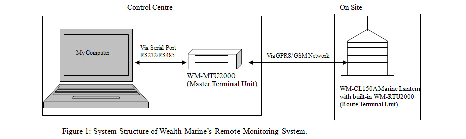
Basically, Wealth Marine's Remote Monitoring System consists of 3 main components, namely the Master Terminal Unit (WM-MTU2000), Route Terminal Unit (WM-RTU2000) and a computer hardware/ workstation (PC with window-based Operating System).
-
WM-RTU2000 Route Terminal Unit
Wealth Marine's WM-RTU2000 is being installed inside WM-CL150A LED Marine Lantern. It is capable of changing the flash character of a marine lantern, has an automatic alarm system, and can be readily connected via transmission system to transmit data to the control centre (Master Terminal Unit WM-MTU2000) directly.
This intelligent Route Terminal can also execute instructions preset by the control centre for remote monitoring and control purposes.
Monitoring Features:
-
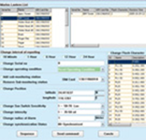
Output Data Transmitted from the lantern (WM-RTU2000):
- Output Data Transmitted from the lantern (WM-RTU2000):
- Flash Character of specific lantern
- Light Intensity of Marine Lantern in working condition
- Name ID/ Serial No. of the Marine Lantern
- Sim card no. of lantern being monitored
- Received time of data report
- Operating Mode of Marine Lantern (Forced 'ON', 'OFF' or 'RESTORE')
- Battery operating voltage
- Operating condition of sun-switch (on/off )
- Position (coordinates) of the lantern
- Synchronisation Mode
-
Automatic Alarm Reporting of WM-RMS2000:
- Malfunction/ irregular flashing of lantern
- Battery operating voltage too low / high
- Intensity of light too low
- Floating buoy moved out of the safety boundary
- Malfunction of sun-switch/ photocell
- In event of lost of contact/communication with buoy
-
WM-MTU2000 Master Terminal Unit:
The Master Terminal Unit (WM-MTU2000) only consists of the MTU2000 communication PCB and a power supply PCB for various distributions (indicators). The size of the housing can be customized to integrate into existing systems with space limitation or as per end-user's preference.
The Master Terminal Unit is located at the control centre and is able to:
- Control the Marine Lantern - 'force' to switch on (during Daytime)
- Control the Marine Lantern - 'force' to switch off (during Night time)
- Remotely change the flash characteristics of Marine Lantern
- Set the upper and lower limits of battery operating voltage
- Remotely receive/ transmit real-time data when required
- Set the safety boundary of the floating buoy
- Set the frequency of data reporting (>4 times per day)
- Set the intensity of the marine lantern
- Set the sun-switch/ photocell (on/off)
Basic features and standard indications on the housing panel includes:
- POWER ON/OFF SWITCH
- POWER ON indicator
- OPERATION indicator
- DATA SENDING indicator
- DATA RECEIVING indicator
- AC POWER SUPPLY (incoming) SOCKET with POWER CABLE
- FUSE PROTECTION
- RS232 or RS485 SERIAL INTERFACE CONNECTOR
- ANTENNA
The MTU2000 communication PCB simply manages the data transmission via the GSM module mounted on the same board. A socket for a local SIM card to be inserted (like mobile phones) is also situated within the same PCB.
The MTU2000 communication PCB provides a display access via RS232 or RS485 serial interface and therefore, connection to a desktop PC or laptop computer would be readily available. The MTU2000 communication PCB and a power supply PCB could be housed inside a compact box (handheld unit) or inside a desktop module.